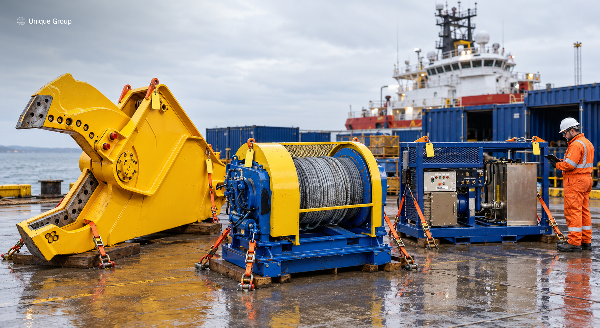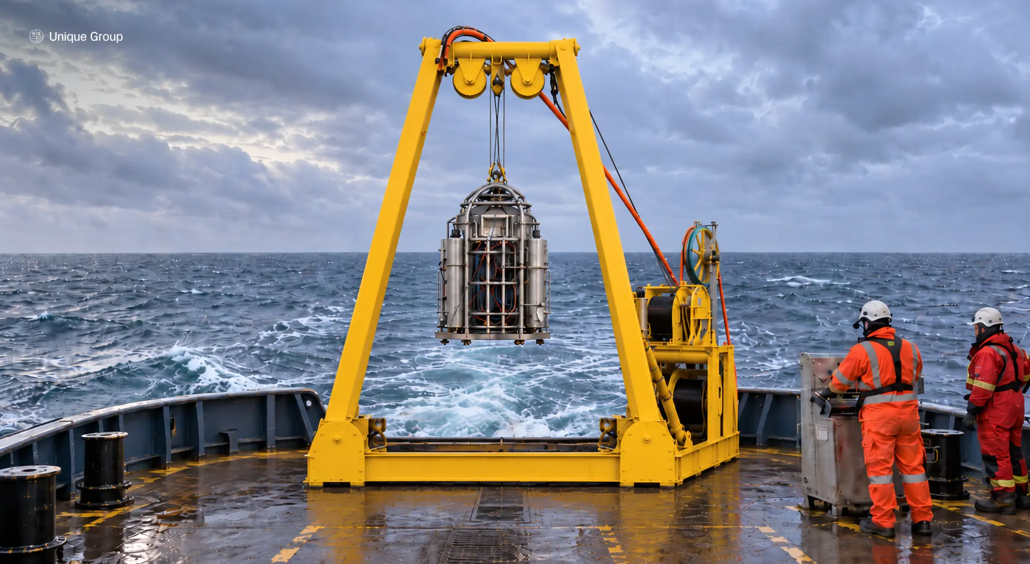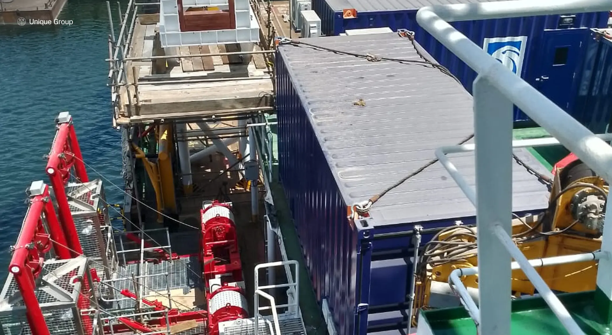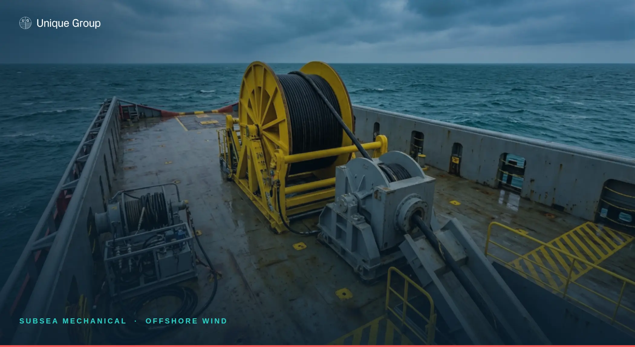
Offshore wind installation places heavy demands on vessel deck planning. Cable reels, winches, spoolers, tensioners, lifting equipment, survey systems, LARS, overboarding arrangements, temporary structures, power units and control cabins may all compete for limited deck space. The challenge is not simply finding room for equipment. The challenge is designing a workable load path, cable path and operating sequence that can be mobilised, tested, operated and demobilised safely.
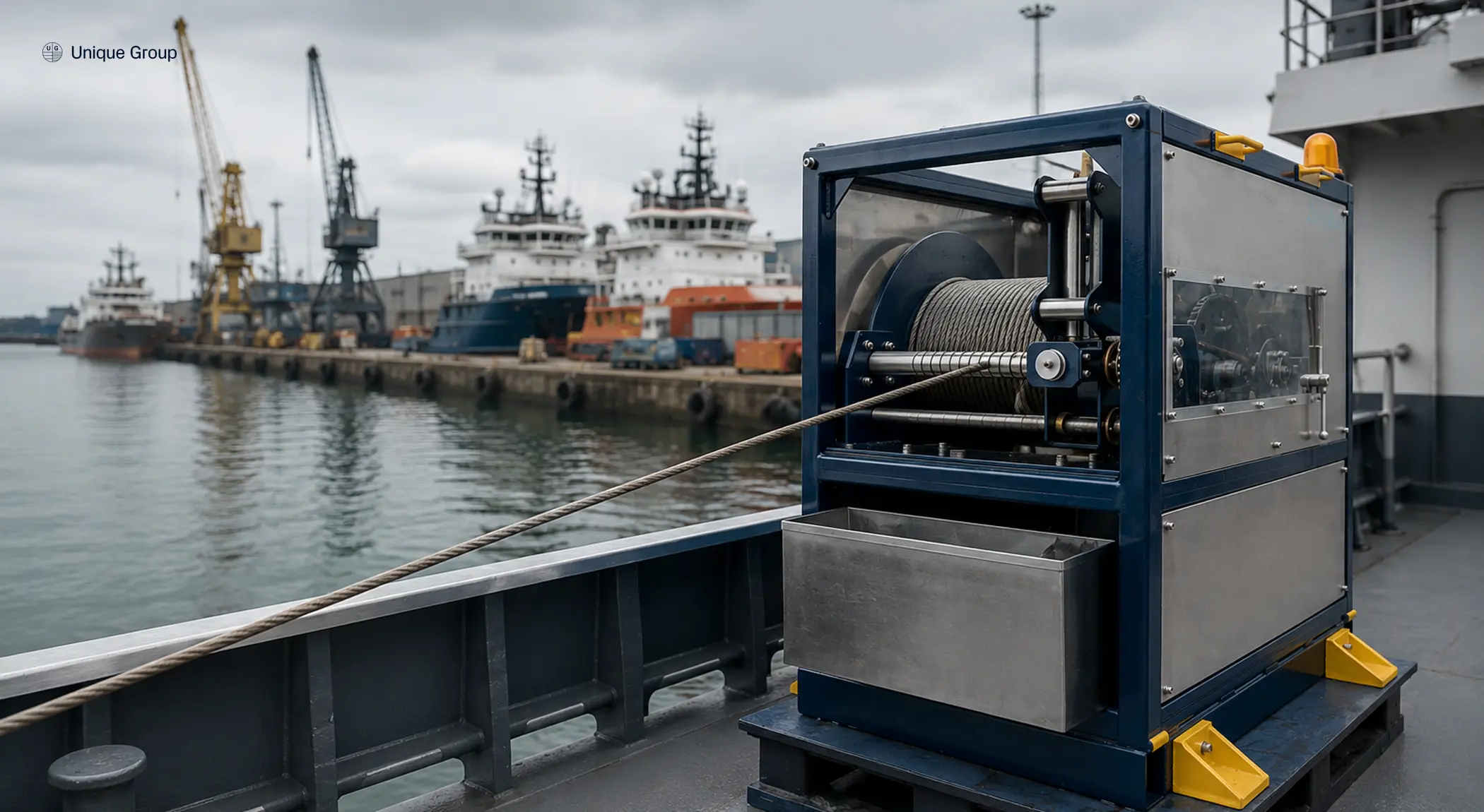
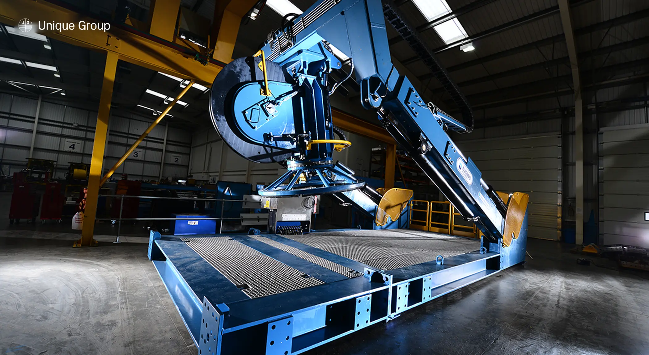
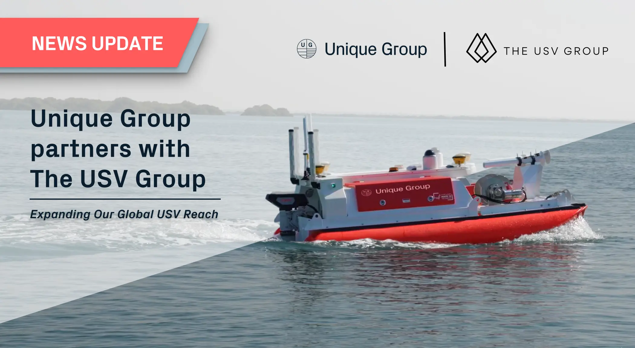
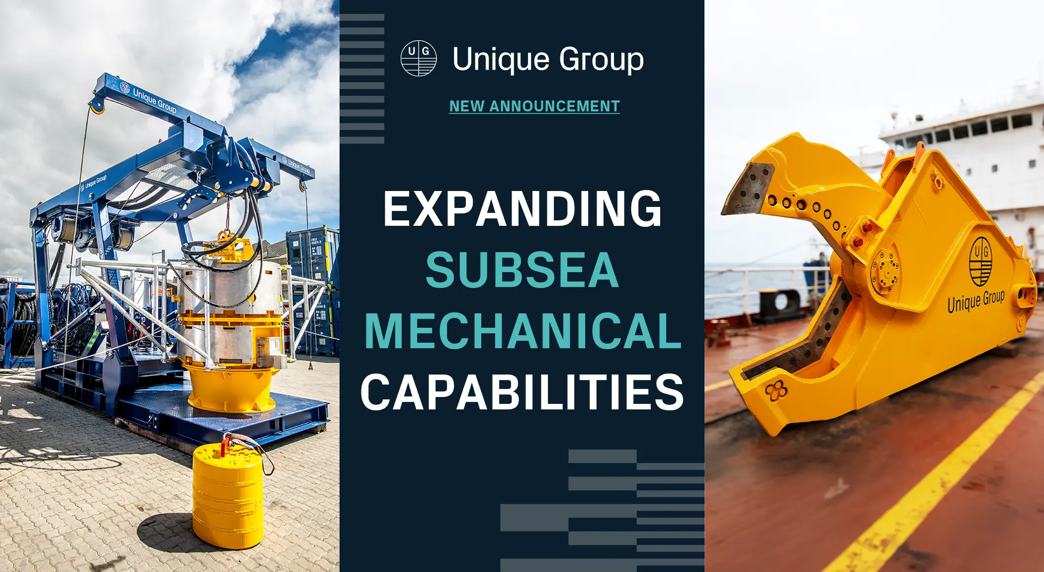
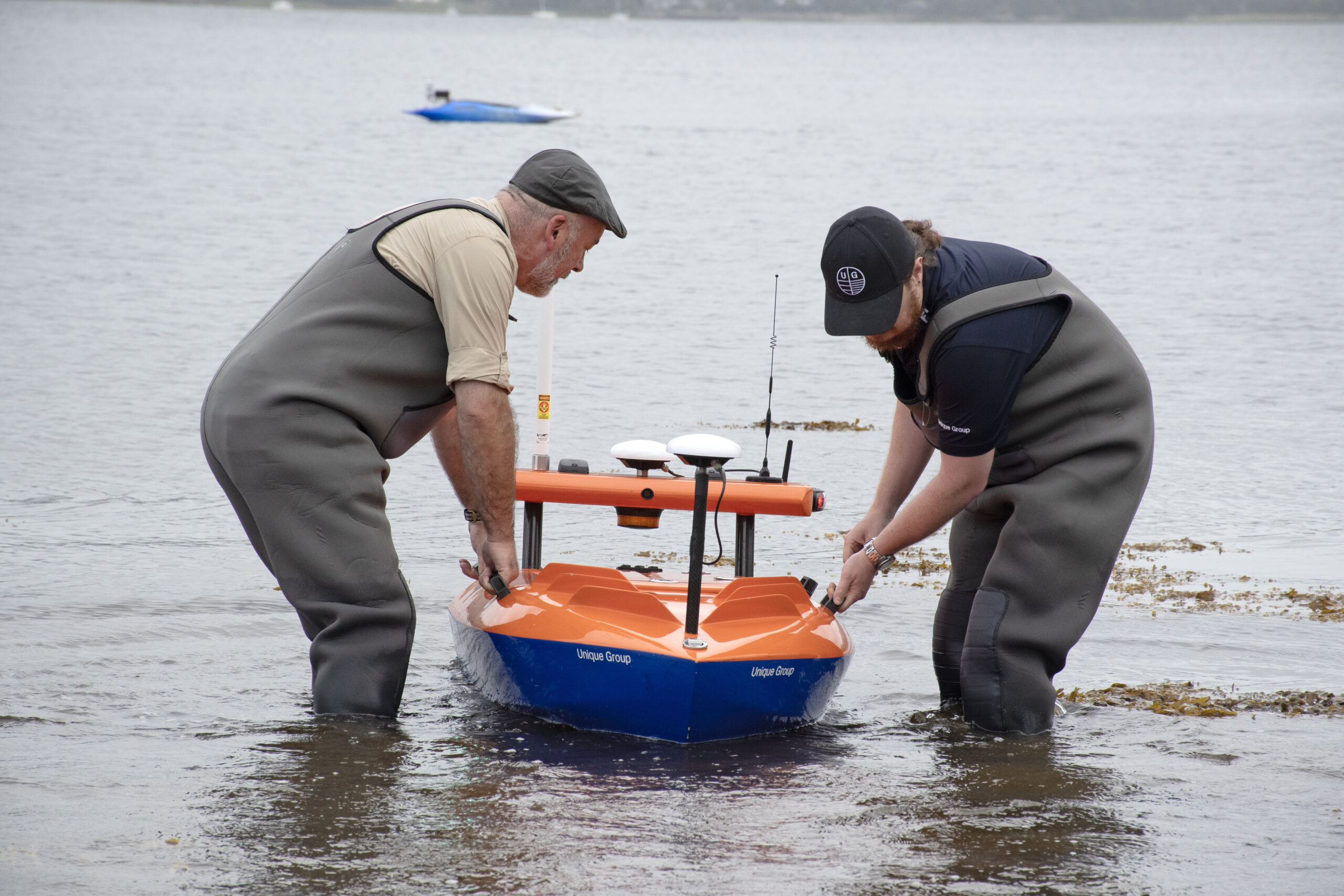
For cable and rope handling on the back deck, Unique Group hires and sells the hydraulic spooler and the Innovo InnoDrive reel drive, and hires out a hydraulic reel stand for controlled rope deployment and retrieval. For survey work in shallow and confined waters, the Uni-Explorer survey catamaran is available for project hire.
Key Takeaways
- A functional back deck spread for offshore wind cable installation typically includes a winch, spooler or reel drive, cable tensioner, level wind, fairleads/chutes, load monitoring, and a matched HPU or EPU.
- Deck layout should be designed around the cable route first — bend radius, tension window and access points — not built by fitting equipment into available space.
- Cable spooling and cable pull-in are related but distinct operations, with different sizing bases and different risk profiles.
- Winch and spooler sizing should be based on the cable datasheet, route geometry and required line pull at each stage — never a generic winch size published without engineering review.
- Mobilisation should be confirmed before the vessel reaches the quay, with certification, sea fastening and control integration checked in advance to avoid late-stage delays.
This article focuses specifically on offshore wind cable installation. For a broader look at winches, spoolers and back deck systems across subsea construction, IRM and decommissioning, see our offshore lifting equipment guide.
As offshore wind scales, back deck configuration becomes more important. The IEA forecasts offshore wind capacity expansion of 140 GW over 2025-2030, with the annual offshore wind market increasing from 9.2 GW in 2024 to more than 37 GW by 2030. As installation activity increases, more projects will require cable handling, pull-in, deployment, retrieval, subsea survey, cable lay support and remedial works.
For installation contractors, cable suppliers and vessel teams, this makes back deck planning a critical part of offshore wind project execution. The equipment spread must be selected around the cable route, vessel constraints, installation procedure, available deck strength and the interfaces between multiple suppliers.
What back deck equipment is typically needed?
| Back deck element | Role in offshore wind installation | Key configuration checks |
|---|---|---|
| Winch | Provides controlled pull, payout, holding or recovery for lines, cable support equipment or installation tools. | Line pull, line speed, brake capacity, drum capacity, control mode, load monitoring and power source. |
| Spooler / reel drive | Supports cable, umbilical, rope or flexible product handling from reel to deck route or overboarding point. | Reel size, cable diameter, cable weight, bend radius, tension window, transport and sea fastening. |
| Cable tensioner / linear cable engine | Applies controlled holding or drive force to maintain cable movement within the required tension window. | Cable diameter range, allowable contact pressure, maximum tension, speed control, grip system, emergency stop response and compatibility with the cable datasheet. |
| Level wind | Supports controlled winding onto a reel or drum and helps maintain consistent cable layering. | Reel width, fleet angle, cable diameter, winding pattern, adjustment range and synchronisation with reel drive speed. |
| Fairleads, deck sheaves, chutes and quadrants | Guide the cable or rope through the deck route and overboarding point while controlling alignment and bend radius. | Minimum bend radius, sheave diameter, side loading, contact surfaces, deck fixing points, cable protection system clearance and inspection access. |
| Cable carousel / turntable | Stores and pays out larger cable lengths where a reel-based solution is not suitable or where project logistics require carousel handling. | Cable length, storage capacity, deck loading, rotation control, access, sea fastening, mobilisation route and interface with tensioners or chutes. |
| Control cabin / local controls | Provides operator interface, alarms, speed control and monitoring. | Visibility, communication, emergency stops, local/remote operation, data logging and integration with vessel systems. |
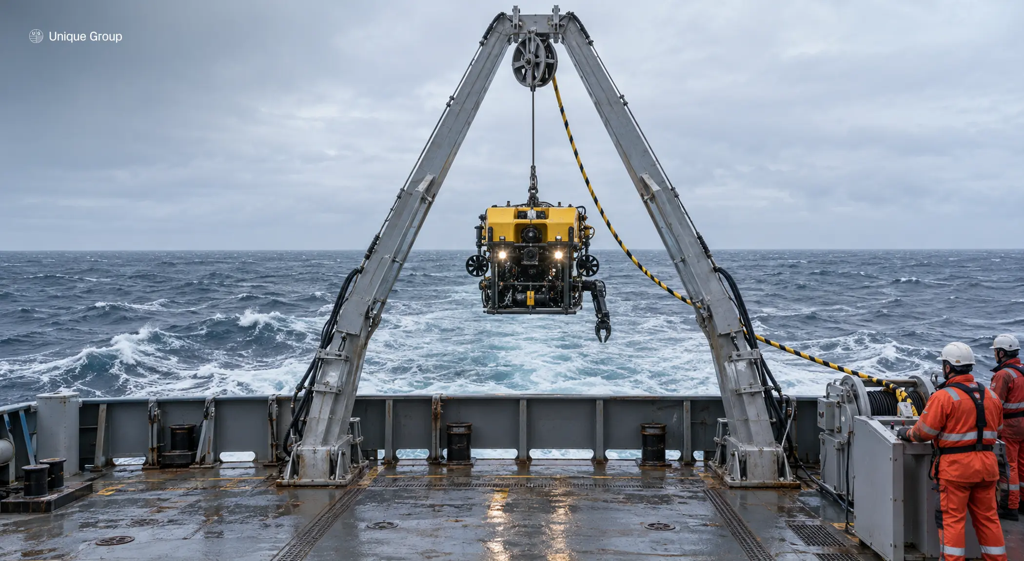
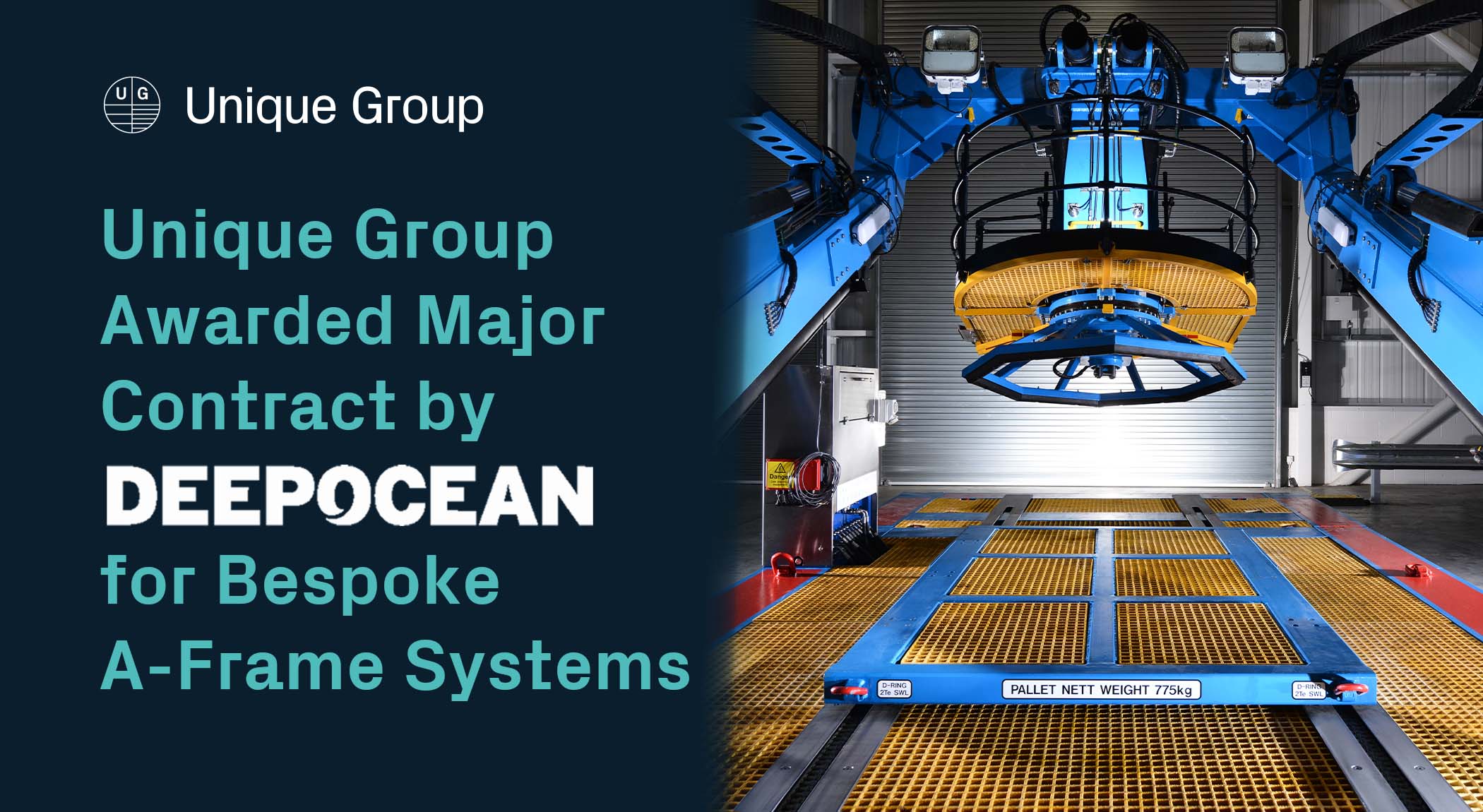
| LARS or A-frame | Launches and recovers ROVs, survey tools, trenching support equipment or other subsea systems. | Payload, deployment envelope, sea state limits, certification and interface with deck layout. |
| Load monitoring | Tracks pull force, speed, payout and other operational data to protect the cable and prove the operation. | Sensor location, calibration, display, logging frequency and reporting format. |
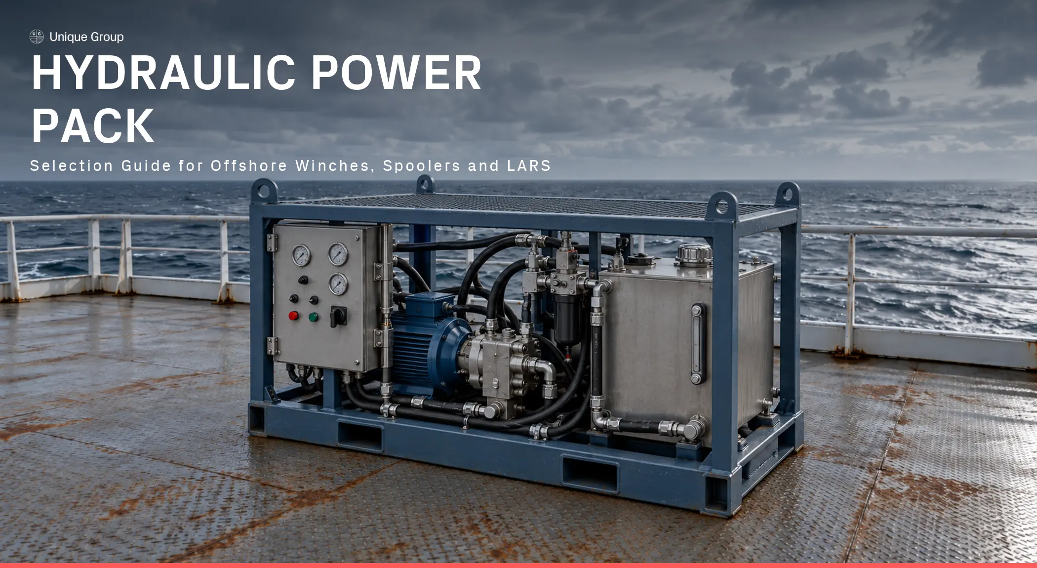
| HPU / EPU / power packs | Provide hydraulic or electrical power for winches, reel drives, tensioners, LARS and associated deck equipment. | Power demand, redundancy, hose or cable routing, cooling, fuel or electrical supply, noise, deck position, access and emergency shutdown integration. |
| Sea fastening, grillage and temporary deck structures | Secure equipment to the vessel deck and distribute loads safely during mobilisation, transit and operation. | Deck strength, weld or bolted interface, load cases, vessel approval, lifting points, inspection access and demobilisation requirements. |
| ROV and survey support spread | Supports touchdown monitoring, route inspection, cable protection checks, subsea positioning and post-lay survey activities. | LARS interface, control cabin position, power and data links, deck access, communication with installation teams and simultaneous operations. |
Vessel deck layout: start with the cable route
A practical offshore wind deck layout normally starts with the cable route, not the equipment list. The team should identify where the cable or rope is stored, how it moves from reel or drum to deck, how it passes through tensioning or guiding equipment, where it leaves the vessel and how operators access inspection and emergency points. The route must respect bend radius limits, prevent uncontrolled side loading and avoid pinch points that would make inspection or intervention unsafe.
The equipment footprint is only one part of the design. The layout must also consider deck loading, crane reach, sea fastening, escape routes, hydraulic or electrical cable routing, compressed air supply if required, operator line of sight, emergency stop positions, manual handling requirements and simultaneous operations.
In offshore wind cable installation, the cable path should also be checked against the cable protection system, overboarding arrangement, touchdown monitoring plan and any interface with J-tubes, hang-offs, foundations, substations or shore landing arrangements. A layout that looks acceptable on a general arrangement drawing may still create problems if the fleet angle, bend radius, access route or emergency recovery sequence has not been reviewed in detail.
Mobilisation and integration planning
Back deck configuration should be confirmed before vessel mobilisation, not adjusted reactively once equipment reaches the quay. A practical mobilisation plan should include deck layout review, lifting and transport planning, sea fastening checks, power and control integration, emergency stop testing, communication checks and function testing before sail-away.
For rental or project equipment spreads, this is also where documentation becomes important. Certificates, inspection records, calibration documents, lifting registers, test reports, interface drawings and operating procedures should be available early enough for client, vessel and class review where required.
Demobilisation should also be considered during the planning stage. Equipment that is difficult to install, inspect or access during mobilisation is often equally difficult to remove safely at the end of the project.
Spooling vs pull-in: related but different operations
| Topic | Cable spooling | Cable pull-in |
| Primary purpose | Managing cable, rope, umbilical or flexible product onto or off a reel, drum or spool in a controlled way. | Applying controlled pulling force to bring cable into position, often toward a hang-off, J-tube, structure or shore interface. |
| Main equipment focus | Reel drive, spooler, level wind, tensioner, overboarding route, controls and monitoring. | Pull-in winch, messenger line, sheaves/fairleads, load monitoring, route protection and termination interface. |
| Main risk to manage | Poor winding, excessive tension variation, bend radius breach, side loading or handling damage. | Exceeding allowable cable tension, uncontrolled movement, alignment issues, structure interface and emergency stop control. |
| Sizing basis | Reel dimensions, cable diameter, weight, bend radius, length and required spooling tension. | Maximum allowable pull tension, route friction, cable weight, geometry, sea state, safety factors and operational procedure. |
Although spooling and pull-in are closely related, they should not be treated as the same operation. Spooling is mainly about controlled storage, payout and winding quality. Pull-in is mainly about applying controlled force through a defined route to bring the cable into its final interface. Each activity may use similar equipment, but the sizing basis, risk profile and control philosophy can be different.
Winch sizing for inter-array cable support
Inter-array cable work requires conservative engineering. A technical article should not publish a generic “right winch size” because required pull depends on cable design, route, vessel setup, interface geometry, seabed interaction, water depth, friction, weather window, cable protection system, allowable tension and the installation procedure.
For cable pull-in or installation support, the winch and spooler package should be reviewed against:
- Cable datasheet, including outside diameter, weight in air/water, minimum bend radius, maximum allowable tension and termination details.
- Route geometry, including overboarding point, sheaves, chute, touchdown point, J-tube or structure interface and vessel position.
- Required line pull at each stage, not only the maximum theoretical pull.
- Line speed and acceleration limits, especially where smooth tension control is important.
- Load monitoring and data logging requirements to demonstrate that cable limits were not exceeded.
- Emergency recovery procedure and failure modes, including brake behaviour and backup power if specified.
- Applicable standards, client specifications, vessel class requirements and inspection/certification documentation.
Common back deck challenges in offshore wind
| Challenge | Why it matters | Mitigation approach |
| Limited deck space | Cable reels, winches, power units, controls, ROV systems and lifting equipment can create congestion. | Build the deck layout around load path, access, escape routes and mobilisation sequence. |
| Cable bend radius control | Exceeding bend radius can damage cables and cause installation delays. | Use compatible sheaves, chutes, tensioners and route geometry; verify against the cable datasheet. |
| Tension control | Excessive pull force can exceed cable limits; unstable tension can increase risk during pull-in or lay. | Specify load monitoring, controlled winch speed and documented tension windows. |
| Interface management | Multiple contractors may supply vessel, cable, winch, tensioner, ROV, trenching or burial equipment. | Reduce interfaces by packaging equipment where possible and agreeing clear responsibilities. |
| Certification and inspection | Offshore operations require traceable documentation and often client/class approval. | Confirm certificates, lifting registers, inspection status, test records and project standards before mobilisation. |
| Mobilisation schedule | Late deck changes can cause vessel delays. | Use proven rental packages where appropriate and complete fit-up, function testing and integration checks before sail-away. |
| Power and control integration | Winches, reel drives, tensioners, survey equipment and LARS may have different hydraulic, electrical and control requirements. | Confirm power demand, hose and cable routing, emergency stops, communications and control interfaces before mobilisation. |
| Sea fastening and deck loading | Heavy equipment, reels and temporary structures can introduce concentrated loads that exceed deck limits if not properly engineered. | Check equipment weights, load cases, grillage design, deck strength and vessel approval requirements before installation. |
| Simultaneous operations | Cable handling, lifting, ROV launch, survey work and vessel positioning may happen in overlapping work areas. | Plan exclusion zones, communication protocols, emergency access, line of sight and safe sequencing between teams. |
Link to cable burial and excavation content
Back deck planning should connect with the broader cable protection workflow. After cable lay or pull-in, the project may require trenching, deburial, seabed levelling, route preparation or remedial excavation. Unique Group’s controlled mass flow excavation article explains non-contact seabed sediment removal for cable trenching, de-burial and related subsea infrastructure work.
For offshore wind installation support, share your cable data, reel details, vessel deck layout and project procedure with Unique Group. Our offshore equipment specialists can help you configure winches, spoolers, LARS, load monitoring systems and back deck equipment for safe cable handling, pull-in and subsea support operations.
Frequently Asked Questions
What is back deck equipment in offshore wind?
It is the vessel deck equipment used to handle, deploy, pull, spool, recover and monitor cable, subsea tools and installation equipment. It can include winches, spoolers, reel drives, tensioners, LARS, control systems and lifting accessories.
What is the difference between cable lay and pull-in?
Cable lay is the controlled deployment of cable along a route. Pull-in is the controlled application of pulling force to bring a cable into a structure, shore landing, hang-off or other interface.
How do you size a winch for inter-array cable?
You size it from the cable datasheet, maximum allowable tension, route geometry, expected friction, water depth, installation method, safety factors, line speed, control requirement and monitoring plan. A generic winch size should not be published without engineering review.
Why is load monitoring important?
Load monitoring tracks pull force, payout, speed and other operational data throughout the pull-in or lay. It verifies that the cable and equipment stay within specified tension and load limits, and provides a documented record proving the operation stayed within those limits.
Why is sea fastening important for offshore wind back deck equipment?
Sea fastening helps secure equipment during mobilisation, transit and offshore operation. It also helps distribute loads into the vessel deck and supports client, vessel or class approval where required.
What information is needed before configuring a back deck spread?
Typical inputs include cable datasheets, reel details, deck layout, vessel deck loading limits, crane reach, overboarding arrangement, project procedure, power availability, certification requirements and mobilisation schedule.