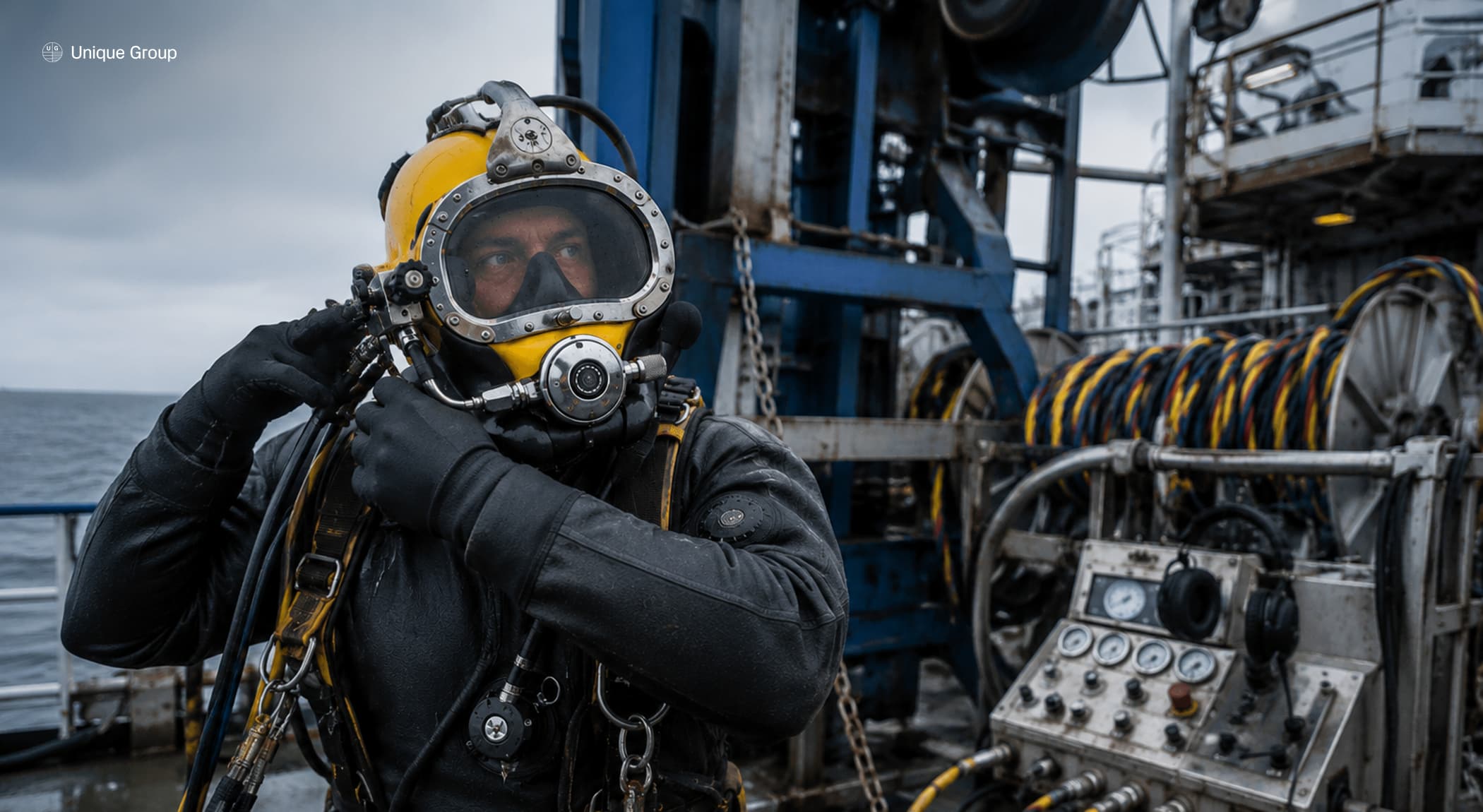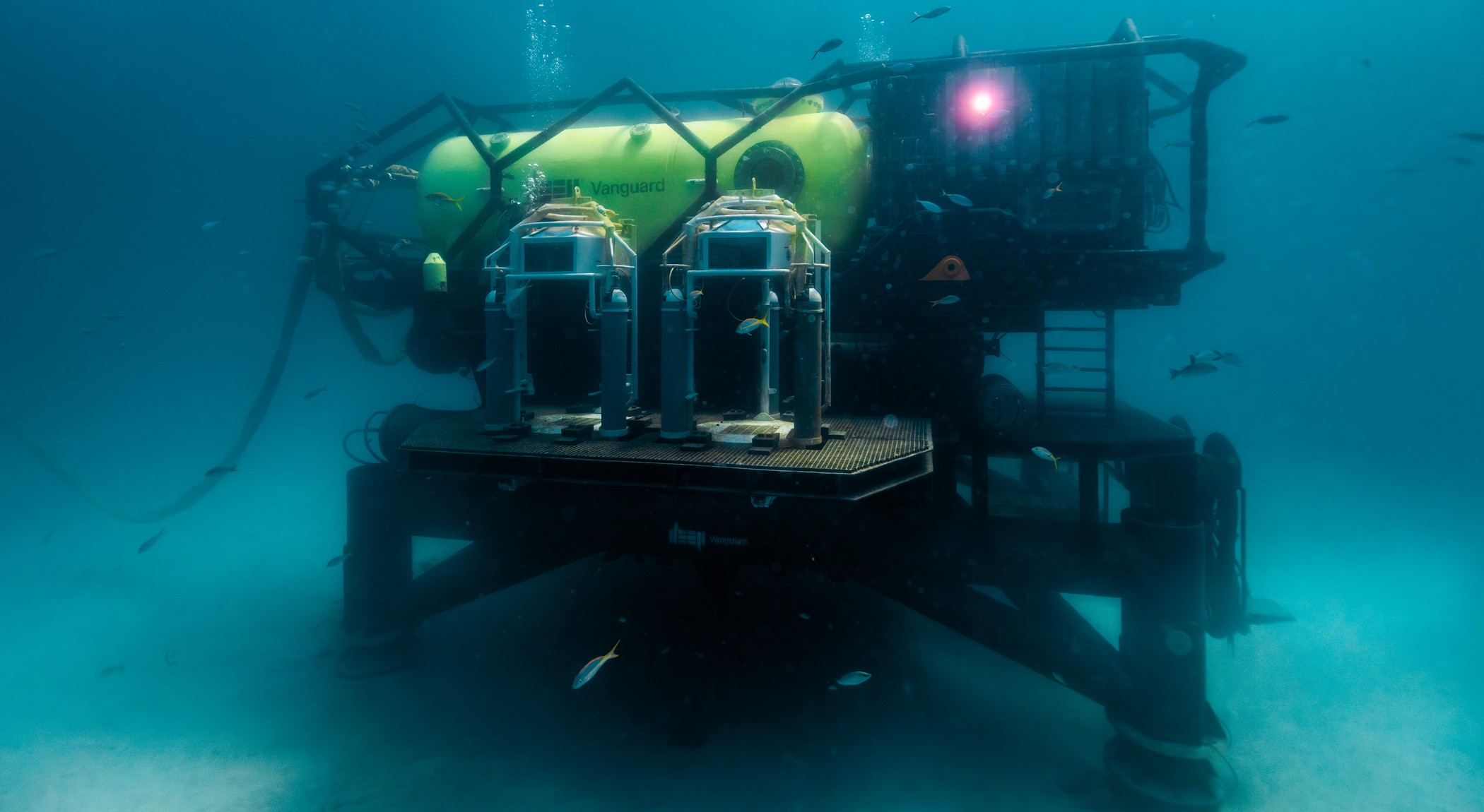
The diving bell, or submersible decompression chamber (SDC), is the primary life support transfer vehicle in a saturation diving spread. It carries divers from the deck compression system to the working depth and back, maintaining them at pressure throughout. The system responsible for this is the diving bell handling system, or DBHS: one of the most engineering-intensive components of any saturation diving spread. This guide covers how diving bell handling systems work, key engineering requirements, and the IMCA and classification standards that govern their design.
What Is a Diving Bell Handling System?
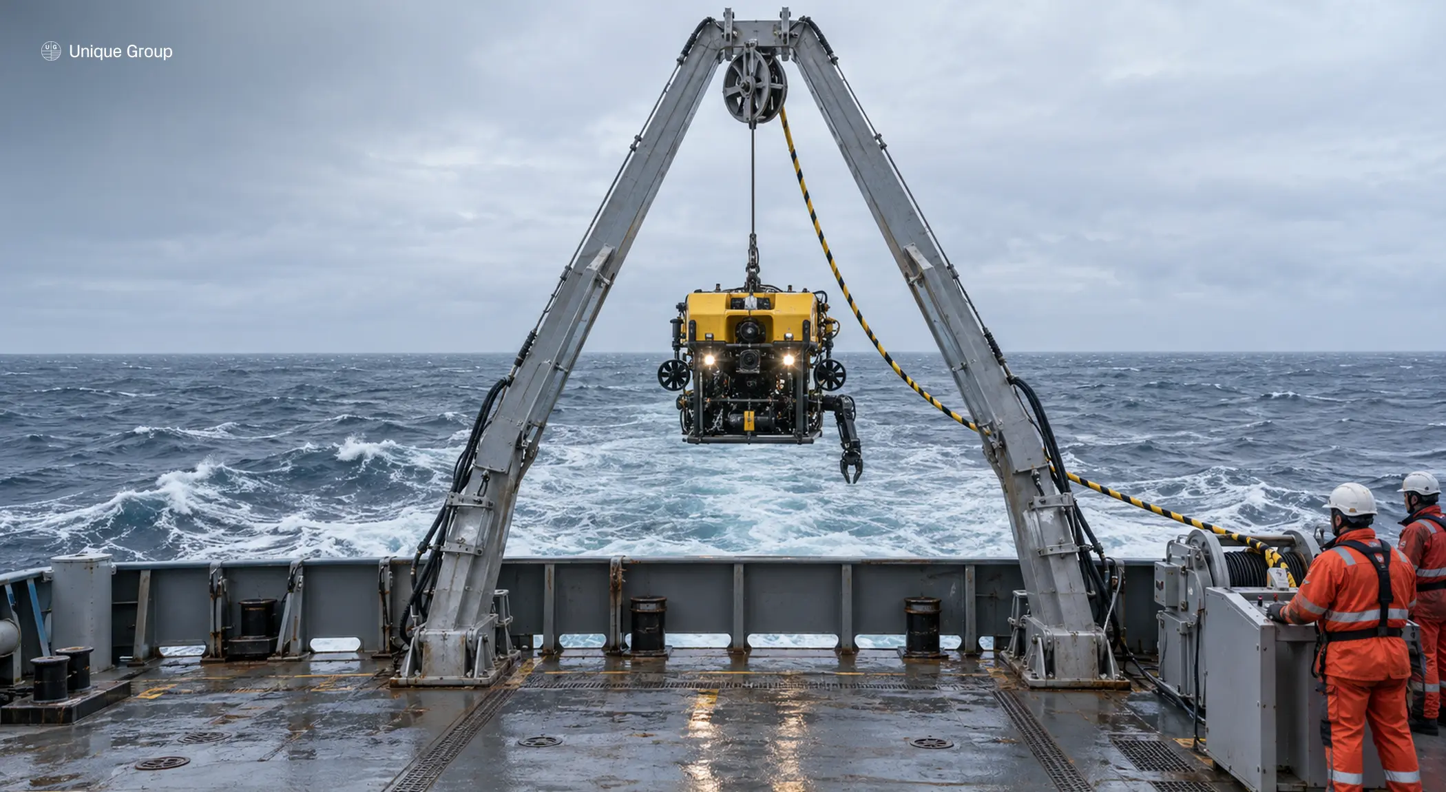
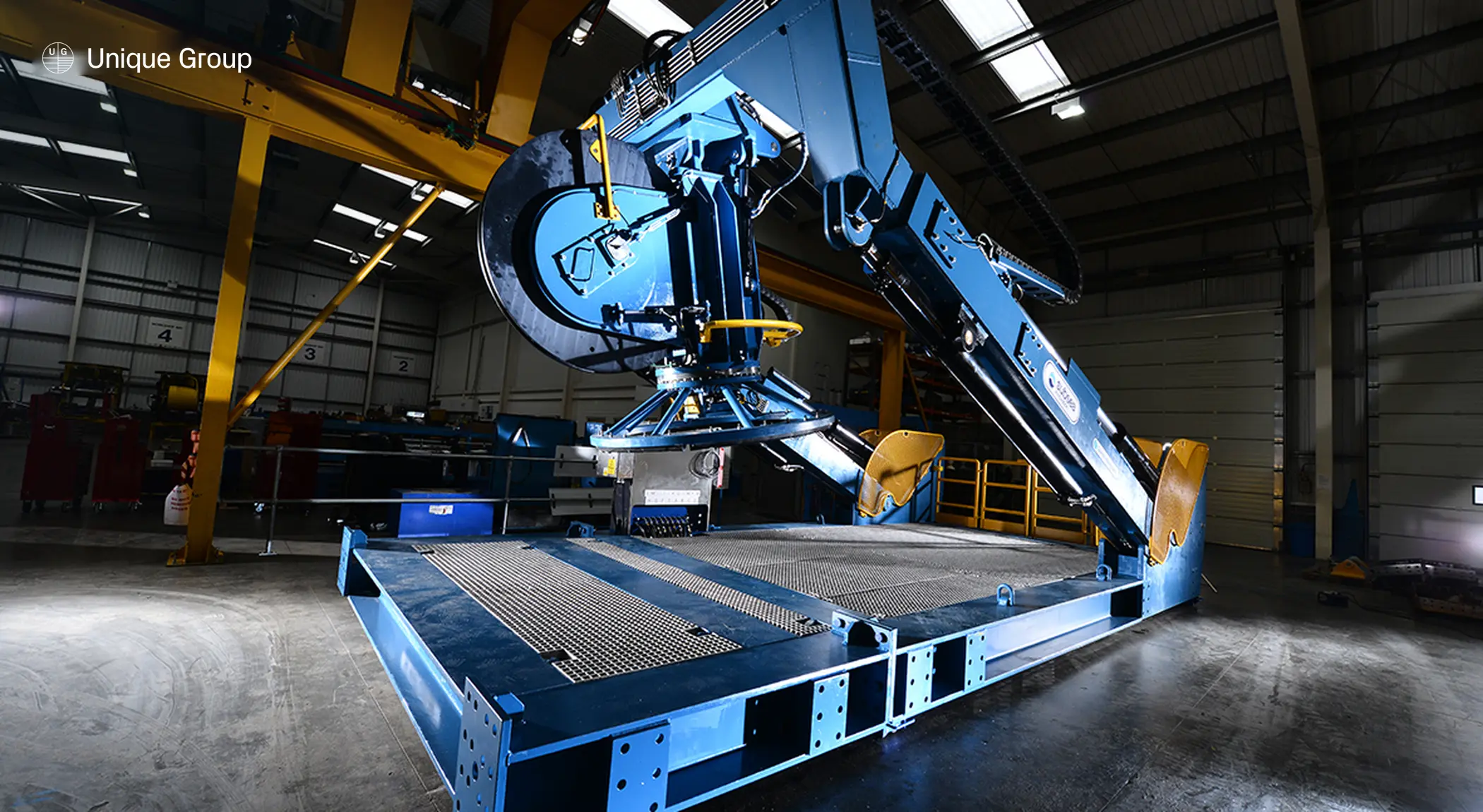
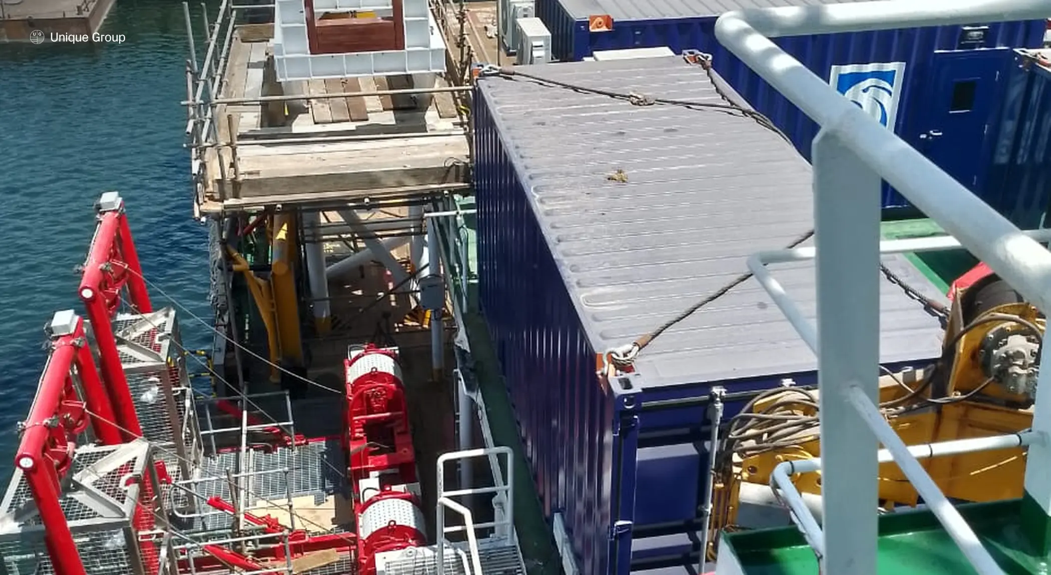
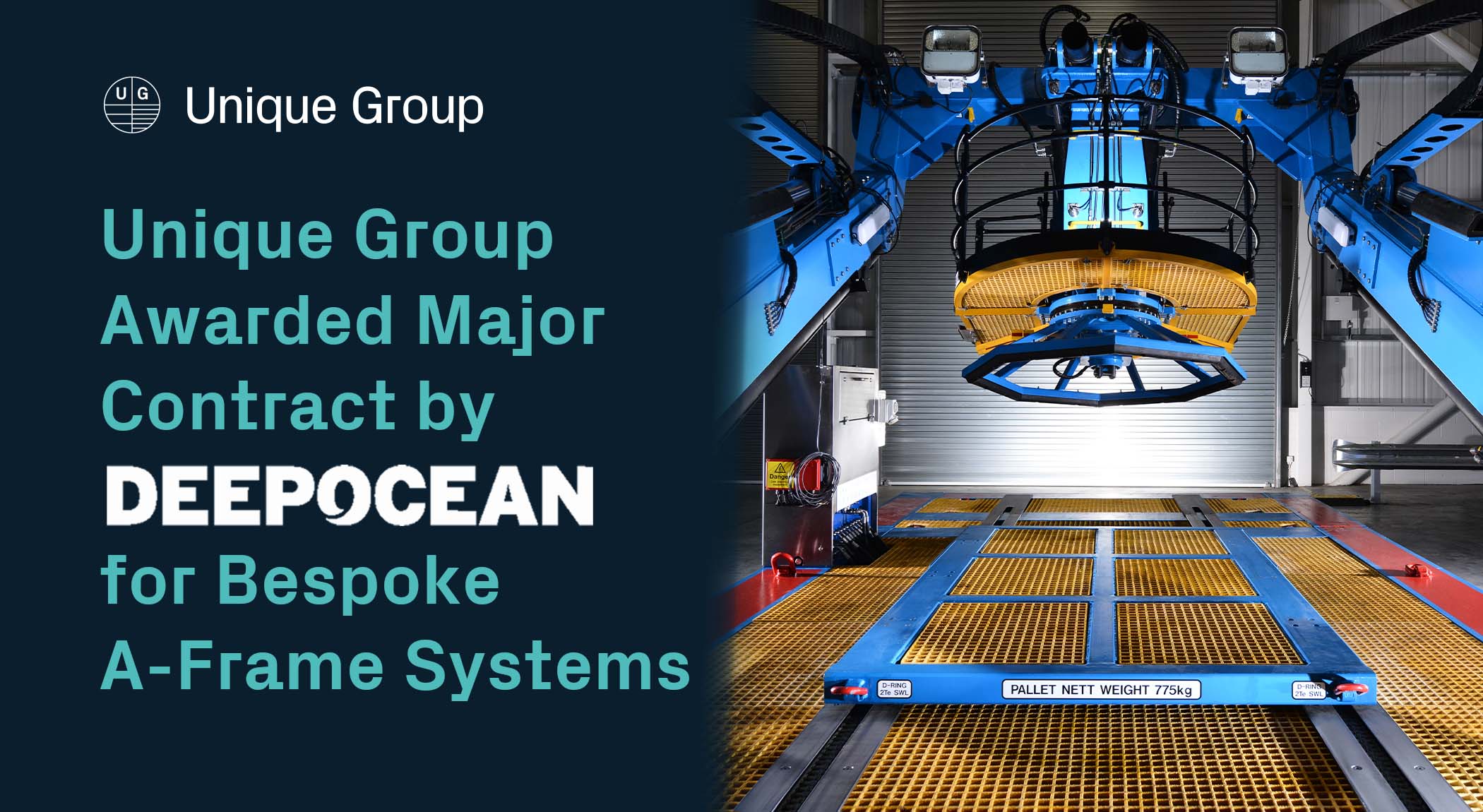
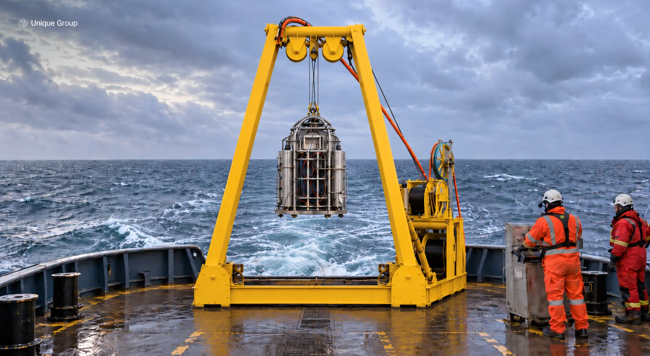
A DBHS is a purpose-designed LARS for the SDC. It consists of the structural framework from which the bell is suspended, a primary lifting winch, an umbilical winch, a guide wire or bell cursor system, a hydraulic power unit, and an operational control station. Configurations vary: some systems use a conventional clump weight and guide wires, while others use alternative multi-wire arrangements without a clump weight. The handling system is structurally integrated with the vessel and deploys the bell either through a moonpool or over the vessel’s side, and must handle the dynamic loads imposed by vessel motion at the design sea state.
Unlike cargo handling or ROV LARS, a diving bell LARS is a personnel-lifting system forming part of a saturation diving system. Its design must address single-failure tolerance, safe personnel lifting, secondary bell recovery following failure of the primary recovery system, and documented emergency retrieval procedures.
Key Components
| Component | Function | Notes |
|---|---|---|
| A-Frame or Gantry | Suspends and deploys the bell, over-side or through a moonpool | Structural frame designed to DNV or equivalent standards |
| Primary Lifting Winch | Handles the main load wire suspending the bell | Separate from the clump-weight winch on conventional configurations |
| Umbilical Winch | Maintains constant tension on the bell umbilical | Independent of the main hoist’s heave compensation |
| Guide Wire or Cursor System | Constrains bell lateral movement during transit | Guide wires on clump-weight configurations, a cursor or trolley on moonpool systems |
| Clump Weight | Tensions the guide-wire system, stabilises and aligns the bell | Deployed below the bell on conventional configurations |
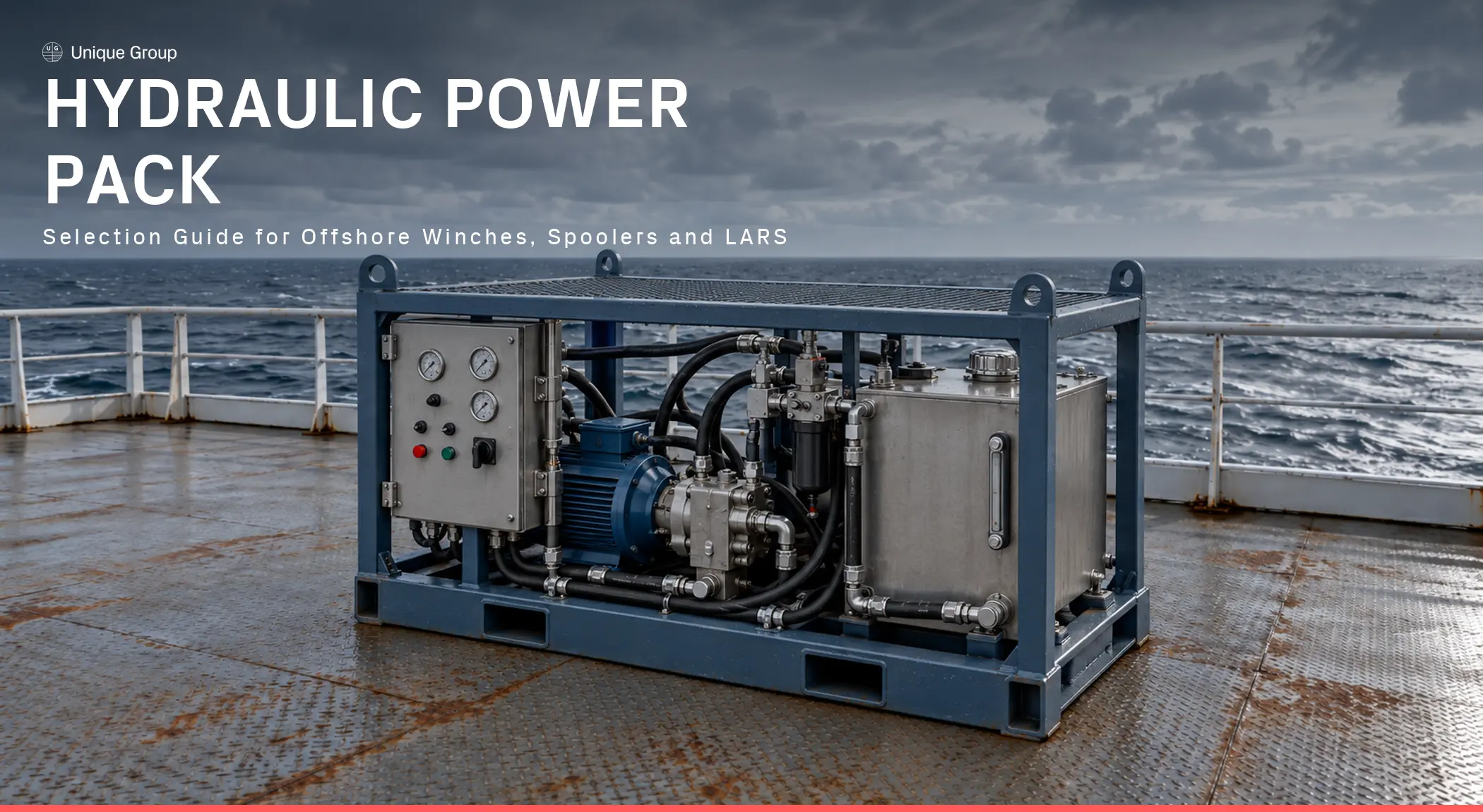
| Hydraulic Power Unit (HPU) | Powers the winches and handling system | Often dual redundant, as on the UG 300 HDS 18 Twin Bell DSV |
The A-Frame or Gantry Structure
The bell is suspended from an A-frame (over-side deployment) or a gantry (moonpool deployment). The structural frame must be designed for the combined static and dynamic loads defined in DNV or equivalent standards, including wave-induced slamming loads in the splash zone. Material specifications, weld quality, and proof load testing requirements are stringent, with the exact witnessing and certification route depending on the applicable class, component, and approval basis.
Primary Lifting Winch
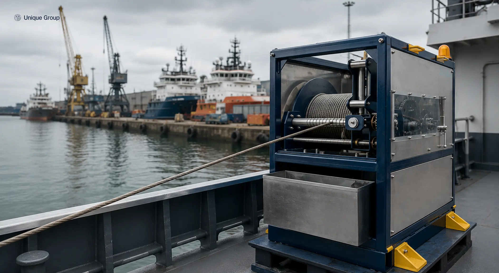
The main winch handles the load wire suspending the bell. On conventional clump-weight configurations, the clump weight is handled by a separate dedicated winch, described below. The main winch must be capable of controlled lowering and hoisting at variable speeds, with mechanisms preventing inappropriate operation or overloading. Wire rope specification is dictated by the design and working load, calculated dynamic effects, minimum breaking load, and the applicable rope factor for personnel lifting applications.
Umbilical Winch and Constant Tension System
The diving bell umbilical supplies power, breathing gas, communications, hot water, and video. An independent umbilical winch maintains constant tension on the umbilical during deployment, following the bell’s movement and preventing slack accumulation during heave cycles. This is separate from active heave compensation (AHC) on the main bell hoist, which some higher-specification spreads use to manage the bell’s own suspension relative to vessel motion.
Guide Wire System
In conventional clump-weight arrangements, the bell travels along tensioned guide wires extending between the topside handling arrangement and the clump weight, passing through guide rollers or fairleads on the bell frame that constrain lateral movement and rotation during lowering and recovery. The clump weight tensions the guide-wire system. This reduces bell swing and risk of impact with the vessel hull as vessel heave and current act on the system. On moonpool systems, a bell cursor or trolley arrangement often performs a similar guiding role through the moonpool and splash zone. During the splash zone transit, the guide wire or cursor system plays a critical role in maintaining controlled bell position.
Clump Weight
The clump weight is deployed below the bell and maintains tension in the guide-wire system, helping to stabilise and align the bell during its guided descent and ascent. The clump weight is sized for adequate stability in the design sea state and current conditions. Its suspension wire is managed by a dedicated winch enabling independent control of bell-to-clump weight spacing.
Hydraulic Power Unit and Control System
The safety requirement is that bell recovery must remain possible following a single failure. Many DBHS designs meet this with dual redundant HPUs, so that a secondary unit can complete the bell recovery if the primary fails during a dive, though this is one architecture that satisfies the requirement rather than the only compliant design. Unique Group’s own saturation diving systems follow this approach: the UG 300 HDS 18 Twin Bell DSV, for example, pairs its DNV-approved, IMCA-compliant 15-ton and 7.5-ton winch combination with a dual redundant power pack as standard. Modern control systems may also incorporate remote emergency-stop functions and operational data logging, depending on the system specification.
Sea State Operability and Design Criteria
The environmental operating envelope of a DBHS is a key commercial specification, and may be characterised by significant wave height (Hs), wave period and direction, vessel motion response, current, and other relevant environmental parameters. Greater operability can translate into more available working time offshore. AHC-equipped bell handling systems can extend the operating window meaningfully beyond a conventional system, and the specific figure a given DBHS achieves is a differentiator worth confirming against the manufacturer’s classed operating envelope rather than assuming a generic industry figure.
Design criteria require dynamic loads during bell deployment to be calculated for the design sea state, accounting for vessel heave, pitch, and roll. Snap load analysis is critical: if the bell wire goes slack during a vessel heave and re-engages abruptly, the resulting load can substantially exceed the corresponding steady-state suspended load. The exact dynamic amplification depends on relative velocity, suspended mass, rope stiffness, and system compliance, and requires a system-specific dynamic analysis rather than a generic multiplier. Wire specification, winch capacity, and structural design must accommodate worst-case snap load scenarios.
Certification and Regulatory Standards
| Standard / Code | Issuing Body | Scope |
|---|---|---|
| DNV-RU-OU-0375 | DNV | Rules for classification of complete diving systems, including component certification, plan approval and survey |
| DNV-OS-E402 | DNV | Technical requirements and guidance for the design, construction, certification and classification of surface-orientated and saturation diving systems |
| IMCA D024 | IMCA | DESIGN guidance for saturation (bell) diving systems, including bell handling and recovery arrangements |
| IMCA D018 | IMCA | Initial and periodic examination, testing and certification of diving plant and equipment |
| IMCA D077 | IMCA | Prevention and mitigation of lost or stricken diving bell emergencies |
| MSC.548(107) | IMO | International Code of Safety for Diving Operations, 2023 |
| HSE ACOP L103 | UK HSE | Approved Code of Practice and guidance for commercial diving projects offshore |
DNV-RU-OU-0375 (Diving systems) provides the classification framework for complete diving systems, including certification of relevant components and materials. DNV-OS-E402 provides the associated technical requirements and guidance for diving-system design, components, testing, certification, and classification, and is complementary to the 2023 IMO Diving Code. DNV approval and survey may include witnessed testing as required by the applicable certification and classification scope. Equivalent certification is also available through ABS and Lloyd’s Register, depending on the vessel’s class society.
IMCA D024 (Design for saturation (bell) diving systems) sets out design requirements for bell handling systems, including a dedicated section on launch and recovery, and works alongside the 2023 IMO International Code of Safety for Diving Operations (MSC.548(107)), which covers design, construction, and survey of diving systems including LARS. IMCA D018 covers the examination, testing, and certification of diving plant and equipment, and IMCA D077 provides specific guidance on the prevention and mitigation of lost bell emergencies. Flag state and coastal state regulations add jurisdiction-specific requirements: HSE ACOP L103 (Commercial diving projects offshore) for UK North Sea operations.
Unique Group’s UG 300 HDS 18 Twin Bell DSV and UG 300 HDS 15 Single Bell Modular DSV are engineered in accordance with applicable DNV requirements and IMCA guidance.
Unique Group’s mobile saturation systems are designed for rapid mobilisation with a minimal deck footprint, supporting projects where equipment needs to deploy quickly and integrate with existing vessel arrangements.
Conclusion
The diving bell handling system is the safety-critical backbone of any saturation diving spread. Its design must balance structural load capacity, dynamic sea state performance, redundancy, and compliance with IMCA, DNV, and flag state requirements. Selecting a handling system supplier with proven manufacturing, testing, and applicable classification and certification capability is a prerequisite for any serious saturation diving contractor or vessel owner.
Explore Unique Group’s saturation diving system engineering at the DSV saturation systems page or contact the team to discuss handling system specifications for your project.
Frequently Asked Questions
What is the difference between a diver LARS and a diving bell LARS?
A diver LARS handles individual surface-supply divers using a diving stage or basket, typically in air, nitrox, or mixed-gas diving at shallower depths. A DBHS handles the complete submersible decompression chamber, transporting multiple divers at pressure to the saturation working depth the system is rated for. A diving bell LARS is subject to additional requirements associated with closed-bell operation, pressure transfer, primary and secondary bell recovery, and emergency retrieval, reflecting its role within a saturation diving system.
How often must a diving bell LARS be proof load tested?
Testing requirements vary by component and test type rather than following one blanket rule. Structural proof loading, functional testing, and periodic in-service examination each sit within the survey programme defined by the applicable class rules, typically DNV-RU-OU-0375 and DNV-OS-E402 for a DNV-classed system, alongside IMCA D018 for the examination, testing, and certification of diving plant and equipment. The exact test factors, intervals, and scope should be confirmed against the specific system’s approved survey programme rather than assumed. Additional examination or re-testing may be required following modification, repair, overload, damage, or an incident, depending on the affected component and applicable class or competent-person requirements.
What causes snap loads in bell handling systems and how are they mitigated?
Snap loads occur when the bell wire goes slack as the vessel heaves downward and then re-engages abruptly. The resulting shock load can substantially exceed the steady-state suspended load, with the exact amplification depending on the specific system’s dynamics. Mitigation measures include appropriate heave-compensation or hoist-control strategies where fitted, maintaining operation within the approved environmental envelope, and designing the wire, winch, and supporting structure for the calculated dynamic loads.
What redundancy is required in a DBHS?
Applicable IMO, IMCA, and classification requirements provide for a primary means of bell recovery and a secondary means capable of recovering the bell following failure of a single component of the primary recovery system. In practice, this typically means recovering the bell using secondary equipment if the primary winch or HPU fails. Emergency recovery procedures must be documented, and crew trained to execute them. The applicable standards require auxiliary power actuation or an appropriate alternative for critical operations such as bell mating, rather than mandating manual override on every control function.